understanding technical drawings
Overzicht van het onderwerp
-
Students of vocational training institutions very often face difficulties in reading and understanding technical drawings, which creates significant obstacles to theoretical and practical training. Traditional teaching methods applied in classrooms are not very effective in solving this problem, but the application of digital design software and 3D printing could make an important positive difference.
Learner qualification levels: EQF 3 and 4
This VET teacher competency development/in-service training scenario addresses the issue of how to provide VET students with the knowledge and ability to read and understand technical drawings using 3D design and 3D printing equipment.
-
If you wish to share your experience in using this OER or you wish to suggest additional resources, please list them here by replying to this forum.
-
-
According to Revised Bloom's Taxonomy (Anderson and Krathwohl, 2001), the learning scenario applies to four areas
- Understanding: Understanding the needs of people in the sales department, especially in the digital part of their work
- Applying: Applying knowledge gained through theory to practice hospitality in real contexts (to create engaging posts and promotion campaigns on Instagram)
- Analysing: Analysing the needs of promoting the hotel and engaging or acquiring new guests through social media (Instagram). Analyzing the needs of the staff in the sales department to gain the proper knowledge and skills.
- Evaluating: Evaluating and reflecting on own performance in practice
-
To accomplish this scenario, it is necessary that students are already prepared from a theoretical point of view and that they possess adequate digital skills. In this way, specialist skills can be integrated into the overall process, and transversal skills can be developed, thanks to a scenario-based approach, collaborative work, and feedback from teachers and peer groups.
The practical part to be produced should not be too complex so that the pedagogical focus does not shift from digital and transversal skills to practical ones.
As for the trainers’ pre-requirements, we suggest implementing the activities suggested in this learning scenario for those who have already mastered basic digital skills in DigCompEdu, as referenced above.
It is, therefore, essential to undertake, beforehand, the IDC-VET self-assessment tool to ensure consistency with this requirement.
-
Teachers explain to students the principles of technical drawing, used symbols and their meanings, drawing methods, layout of projections and other necessary information. Students read the printed drawings provided and explain the information in them.
-
As outlined above, assessment is implemented at each phase above via different methods and approaches aimed at ensuring both validations of competencies, exploitation of digital tools and skills, engagement of learners, and peer-learning.
Tutors are accompanied to exploit digital skills to implement assessment of learning via several methods and tools, including:
● Evidenced-based evaluation
● Peer-review
● Checklist
● Spreadsheets & Slides on Google Drive
● Jamboard on Google for fiving feedback and peer -review
-
It is necessary to start with the first specified activity. Before working with digital drafting software, students should already be able to explain simple drawings. It is very important for students to be able to distinguish lines in drawings and to know what they mean (contour line, axis line, dimension lines, etc.). This activity can be done using both printed drawings on paper and digital drawings displayed on the board with the help of a projector (Figure 1).

Figure 1. Projection of digital drawing on the smart table.
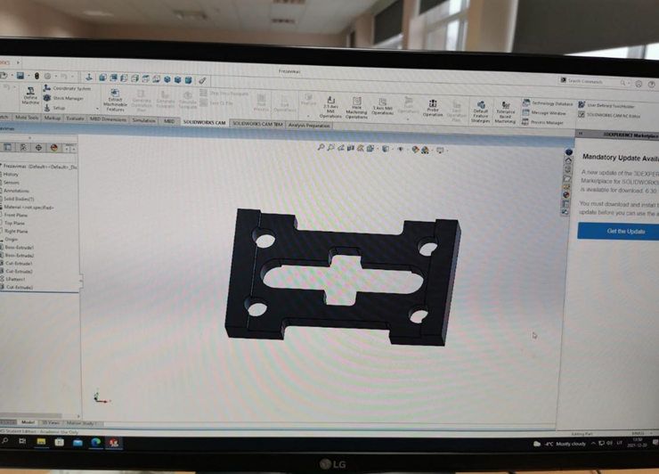
Once students understand the drawing of the part, the next stage of training is to design the part in 3D in a CAD environment. In the example above, this is SolidWorks ( Figure 2 ).
Figure 2. SolidWorks screenUsing 3D design for simple parts is not practical and efficient, but it is very useful for more complex parts where more complex geometric shapes intersect and the intersection points are not straight lines. Therefore, 3D design helps students with weaker spatial thinking.
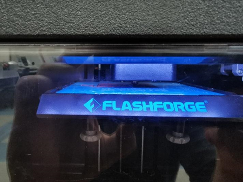
With the ability to design a part in a CAD program and having a 3D printer, it is easy to print a prototype and have it before machining or welding operations. (Fig. 3; 4; 5).

Figure 3. Beginning of 3D printing.

Figure 4. End of 3D printing.

Figure 5. Printed part.
Since the technical capabilities of the printer are much smaller than that of a CNC milling center, the part is printed at 1:5 scale to account for this.
These tools are not mandatory for learning to read drawings, but they greatly facilitate the acquisition of knowledge and, most importantly, compensate for the lack of spatial thinking. With a detailed model in hand, students can visually check that they have understood and completed everything correctly. If not, they correct their mistakes, if yes, they start working on the part.
Most machine tools, like computerized CAM systems, have a part machining model. This is another tool to help ensure that the part will be manufactured according to the drawing (Figure 6).

Figure 6. Milling simulator
The image above shows a milling simulator that simulates a milling operation on the screen. In this way, it is possible to visually assess whether all operations have been performed correctly and whether the produced part will correspond to the drawing. -
- Jeli, Z., Popokonstantinovic, B., & Stojicevic, M. (2016). Usage of 3D Computer Modelling in Learning Engineering Graphics. In (Ed.), Virtual Learning. IntechOpen. https://doi.org/10.5772/65217